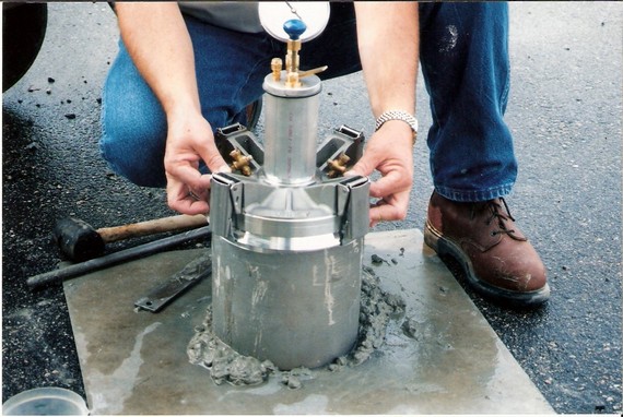
TYPE B PRESSURE AIR METER ASTM C-231
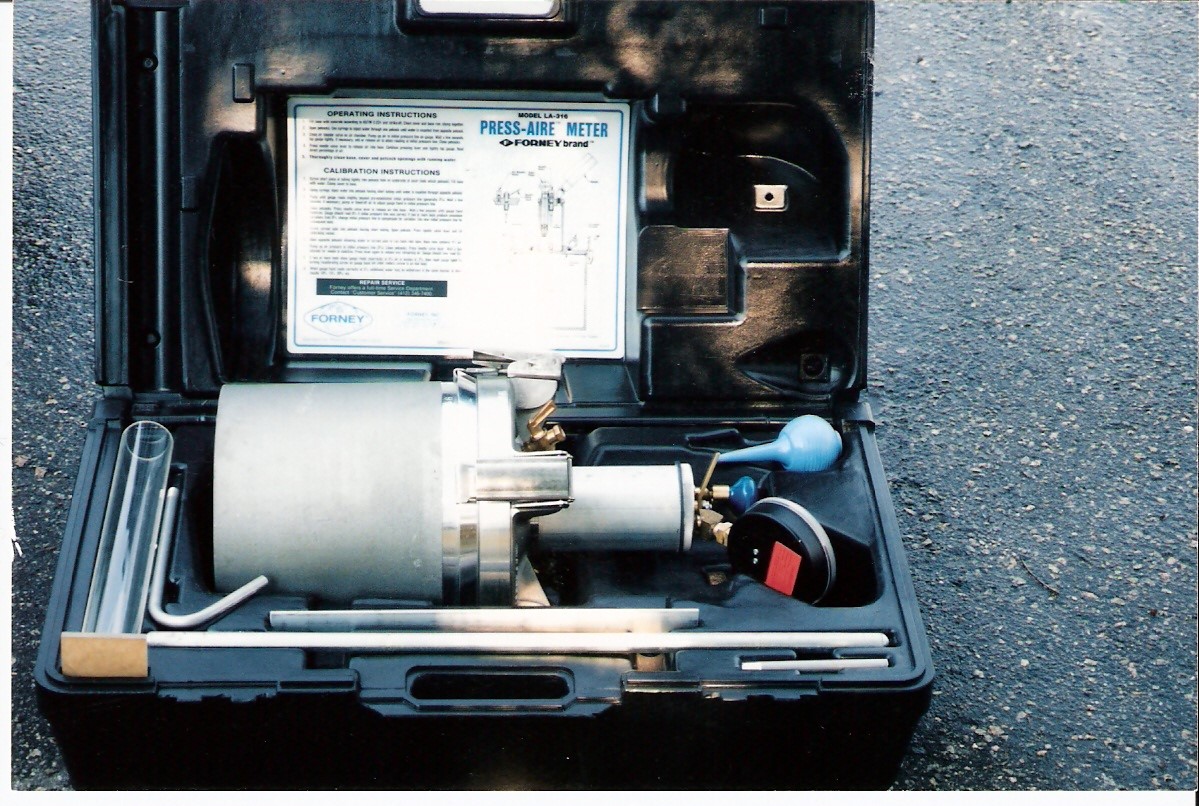
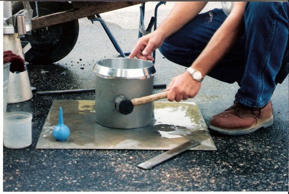
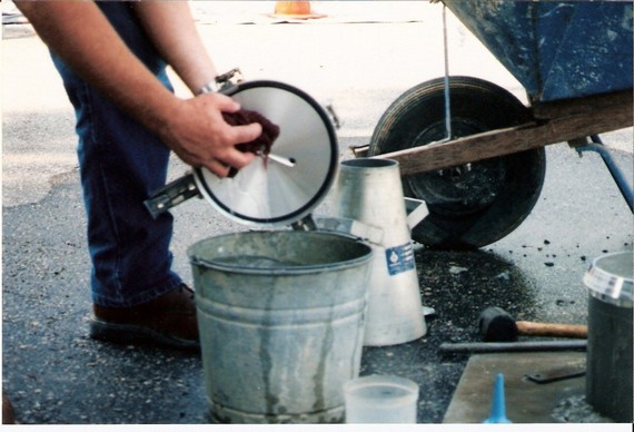
The equipment needed to run the air content test is shown above. Includes: a measuring bowl and cover assembly, a tamping rod, a scoop, a rubber mallet, a strike-off bar, a syringe, and a level surface. Thoroughly remix the sample of concrete prior to testing.
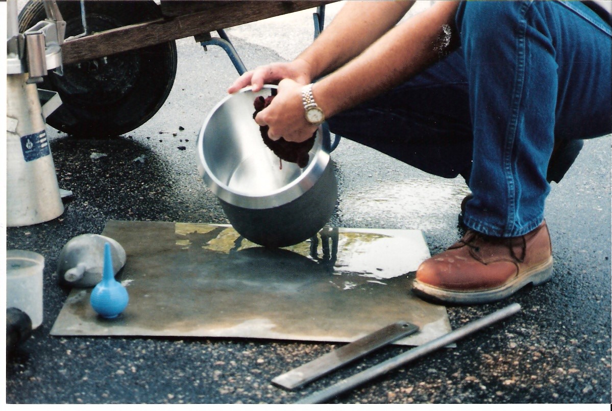
Clean the measuring bowl and all the equipment to be used, drain any excess of water.
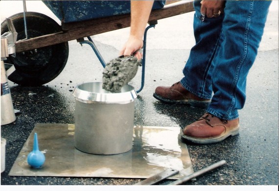
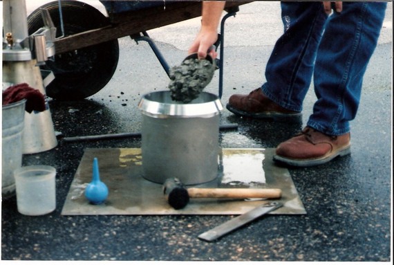
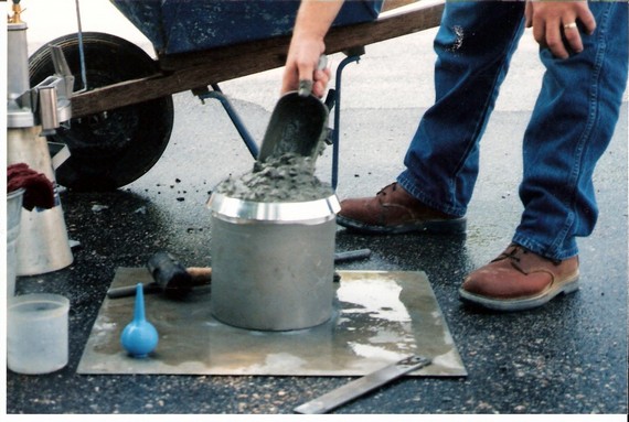
Fill the first layer with concrete to about 1/3 of the volume of the bowl, distribute the concrete evenly.
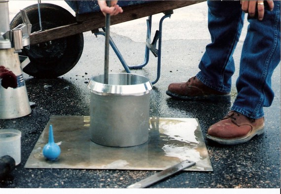
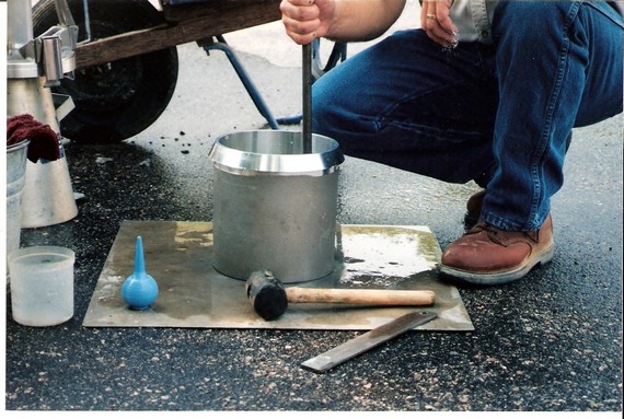
Rod the first layer 25 times. Distribute rodding stokes over the entire cross section of the measuring bowl, penetrating the entire depth of the layer.
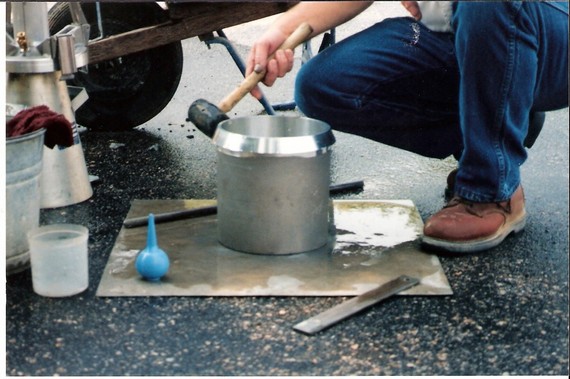
Tap the sides of the measuring bowl 10 – 15 times to consolidate the concrete.
The second layer is to be filled up to 2/3 of the volume of the measuring bowl (this is equivalent to filling up to 2/3 of the height of the bowl), distributing concrete evenly.
Rod the second layer 25 times, penetrating the first layer by 1 in.
Consolidate the second layer by tapping the sides of the bowl 10 – 15 times.
Fill the third and final layer (slightly overfill).
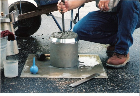
Rod 25 times, the rod penetrating 1 in. into the second layer. Distribute the strokes evenly.
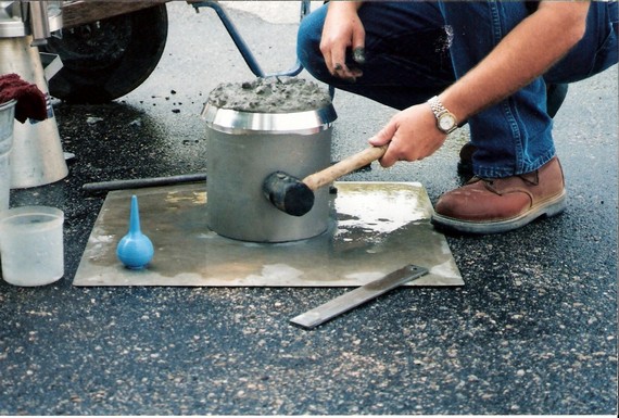
Tap the sides 10 – 15 times to consolidate.
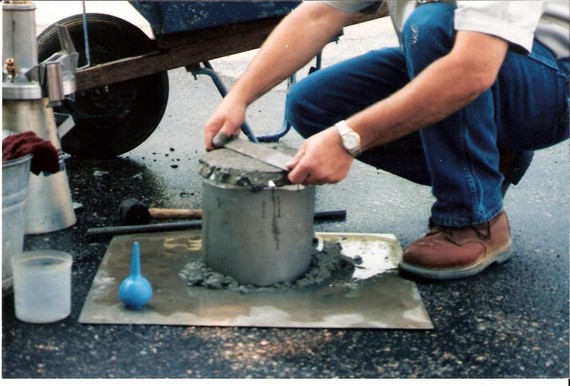
Remove all excess concrete with the strike-off bar, creating a smooth finish.

Clean the rim/flange of any concrete residue. The rim/flange must be clean moist before the cover assembly is applied. A damp rag or towel is helpful.
Moisten and clean the cover assembly gasket to ensure a good seal. Do not clean the lid over the base of the meter.
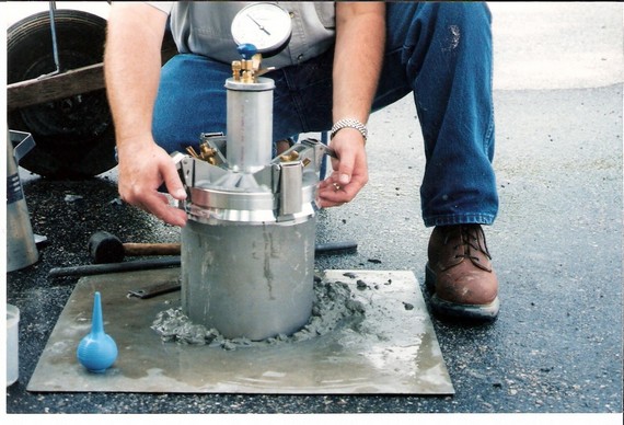
Note: NCDOT requires that both petcocks be closed prior to installing the cover assembly. Close the airbleeder valve (the rounded one on the air chamber, which controls the air pressure in the pump chamber). Install the cover assembly. Use the clamps to secure the cover assembly tightly on to the base. Secure opposite clamps simultaneously.
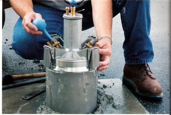
After installing the cover assembly, open both petcocks. Keep the bleeder valve closed (the rounded one located in the chamber). Use the syringe to inject water into one petcock until it flows out the other.

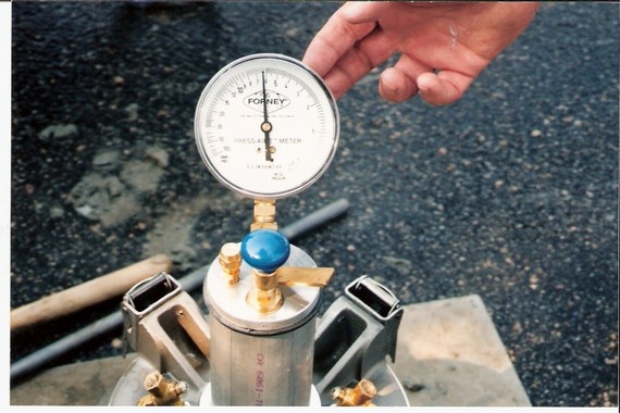
Keep both petcocks open. Check the gauge to make sure there is no prior pressure reading (the needle is in its “hands free” zone). Pump air into the air chamber until the gauge needle reaches the equipment’s “initial pressure line”. Allow a few seconds for the gauge to stabilize. Use the airbleeder valve to adjust the chamber’s air pressure until the gauge reading is at its “initial pressure line” (each equipment can have its own, calibrated, initial pressure line).
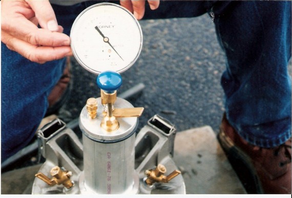
Tap the gauge lightly, again, this will stabilize the gauge needle.
Close the petcocks. Press the air needle valve (the one with the lever) to release air in to the bowl base. Wait for the gauge needle to stabilize. Tap the sides of the measuring bowl with the mallet to relieve local constraints.
Tap the gauge lightly, and then repress air needle valve again to release any trapped air. Tap gauge lightly to stabilize. Read the percentage of air directly off the gauge. Subtract the aggregate correction factor and record.
PRESSURE AIR METER CALIBRATION INSTRUCTIONS
TYPE B
1.
Screw short piece of tubing tightly into petcock hole on underside of cover (note which petcock). Fill base with water. Clamp cover to base.
2.
Using syringe, inject water into petcock having short tubing until water is expelled through opposite petcock.
3.
Pump until gauge reads slightly beyond pre-established initial pressure line (generally 3%). Wait a few seconds. If necessary, pump or bleed- off air to adjust gauge hand to initial pressure line.
4.
Close petcocks. Press needle valve lever to release air into base. Wait a few seconds until gauge hand stabilizes. Gauge should read 0% if initial pressure line was correct. If two or more tests produce consistent variations from 0%, change initial pressure line to compensate for variation. Use new initial pressure line for subsequent tests.
5.
Screw curved tube into petcock having short tubing. Open petcock. Press needle valve lever and fill calibrating vessel.
6.
Open opposite petcock allowing water in curved pipe to run back into base. Base now contains 5% air.
7.
Pump up air pressure to initial pressure line (3%). Close petcocks. Press needle valve lever. Wait a few seconds for needle to stabilize. Press lever again to release any remaining air. Gauge should now read 5%.
8.
If two or more tests show gauge reads incorrectly at 5% air in excess of .2%, then reset gauge hand by turning recalibrating screw on gauge hand (on older meters, screw is on dial face).
9.
When gauge hand reads correctly at 5%, additional water may be withdrawn in the same matter to check results 10%, 15%, 20%, etc.
*** Forney offers a full-time SERVICE REPAIR DEPARTMENT. Contact “Customer Service” @412-346-7400.
TYPE B PRESSURE AIR METER CALIBRATION
The equipment needed to calibrate the Type B meter is shown above. The meter base and lid, 5% calibration cylinder, tubing, and a surface that is stable and level.
Screw the short piece of tubing into petcock hole on underside of cover (note which petcock)
Fill the base with water
Securely clamp the lid onto the base. Alternate side clamps should be tightening simultaneously.
Using syringe, inject water in to petcock having short tubing until water is expelled through opposite petcock.
Pump air meter until gauge reads slightly beyond pre-established initial pressure line.
Wait a few seconds. If necessary, pump or bleed off air to adjust gauge hand to the initial pressure line.
Close the petcocks.
Press needle valve level to release air into base. Wait until gauge hand stabilizes. Gauge should now read 0% if initial pressure line was corrected.
Screw curved tube into petcock having short tubing. Open petcock. Press needle valve level and fill calibrating vessel.
Open opposite petcock allowing water in curved pipe to run back into base. Base contains 5% air.
Pump up air pressure to initial pressure line (typically 3%)
Close petcocks. Leave curved tube attached to lid.
Press needle valve lever. Wait needle to stabilize. Press lever again to release any remaining air. Gauge should now read 5%.
If two or more tests show gauge read incorrectly at 5% air in excess of 0.2%, then reset gauge hand. Remove cover from gauge to make adjustment.
Adjust the gauge hand by turning the recalibration screw on the gauge face. (For airpots issued by the department, the concrete technician should be contacted to make this adjustment).
