• ENGINEERING CONTROL

  • ENGINEERING CONTROL

  •  
     

    USE OF PHOTOGRAMMETRY FOR DETERMINATION OF EXCAVATION QUANTITIES
     
    GENERAL
     
    Aerial survey methods used by the Photogrammetry Unit for determining excavation quantities have been proven to be as accurate as ground survey methods. Use of aerial surveys for this purpose may allow a Resident Engineer to better utilize available manpower. The decision to utilize the Photogrammetry Unit to provide this service should be based on several factors, which are listed below. In general, the safety of NCDOT employees, the quantity of earthwork involved, and extent of acreage under construction must be of sufficient volume to make this type of operation economical.
     
    Factors to Consider Before Requesting the Use of Photogrammetry:
     
    1. Are there safety issues that exist where NCDOT employees are at a higher risk of injury to perform field surveys?
       
    2. Are there 100,000 cubic yards or more of unclassified excavation?
       
    3. Is the workload of the Resident Engineer’s office such that Photogrammetry is needed?
       
    4. Are there environmental concerns that make it cost prohibitive to use Photogrammetry (can only clear small areas at a time)?
       
    5. Does traffic control phasing cause a need for numerous flights?
       
    6. Natural ground and finished excavation must be above water.
       
    7. It is necessary to have the area, to be flown, cleared and grubbed prior to the aerial survey. It is important that all required erosion control measures be installed in conjunction with clearing and grubbing.
       
    8. Cost of ground surveys versus aerial surveys with respect to project topography and complexity must be considered. For a 17 – 20 acre site, the cost for both ground surveys and aerial surveys are approximately the same. As a rule, the smaller the site the more economical it is for ground surveys and the larger the site the more economical it is for aerial surveys. With the introduction of Unmanned Aerial Systems (UAS) within NCDOT, the utilization of this new technology for small construction earthwork sites, borrow pits and stockpiles may be more economical than traditional ground survey.
       
    9. Total turn around time for original and final terrain compilation and earthwork computation will be based upon schedules between the Resident Engineer and Photogrammetry. All efforts should be made to submit final flight request after paving is completed. Delayed requests for final flights may result in less accurate quantities due to erosion and other factors.
       
    10. It should be shown that it is in the best interest of the Department from the standpoint of construction personnel utilization and total construction engineering cost.
       
    11. Aerial photography provides a permanent record of terrain on the date of photography and can be a valuable source of information for verifying earthwork quantities, ground conditions, etc., in the event of disputes or litigation.
       
    12. Safety of field personnel, particularly in areas adjacent to high-speed, heavy traffic volumes, should be a consideration when determining whether aerial surveys should be used.
     
    The Resident Engineer and Division Construction Engineer should decide the method of terrain data collection to be used on a project prior to the Preconstruction Conference. If Photogrammetry is chosen as the most economical or practical method, the State Photogrammetric Engineer’s office should be contacted in writing so that work scoping and scheduling can begin.

    ROLE OF THE CONTRACTOR
     
    The Contractor should be informed at the Preconstruction Conference if photogrammetric methods will be utilized to determine terrain data used for earthwork quantities. Article 225-7 of the Specifications indicates that the decision to use either aerial or ground surveys for excavation quantities is the Engineer’s, but it is important to let the Contractor know as soon as possible since the decision will have a significant impact on his operations. All communication between the Contractor and the Photogrammetry Unit should be through the Resident Engineer.
     
    The Contractor may be required to clear and grub more than the 17 acres included in Article 225-7 of the Specifications, which means the erodible surface will be in excess of that normally deemed desirable for the control of erosion. Projects can and should, if feasible, be flown in stages. The Contractor must simultaneously install all measures required by the plans for the clearing and grubbing phase and have the necessary equipment available to maintain these devices over a relatively large area. The Contractor should be advised that the opening of larger areas to accommodate photogrammetric methods would not affect the areas allowed for grading operations. To ensure high resolution in the aerial photography, the Resident Engineer must prohibit the Contractor from performing any burning on the day a photo mission is scheduled to be flown.
     
    In some instances, the Photogrammetry Unit will not always be able to fly a project before a Contractor is ready to begin his grading operations. In these instances, the Resident Engineer must take the required original terrain data by ground survey methods so the Contractor will not be delayed. The original terrain data representing these areas must then be forwarded to the Photogrammetry Unit prior to or concurrent with the ground control surveys so they can be combined with the aerial survey terrain data for incorporation into the total earthwork computations for the project.
     
    Information to Provide to the Photogrammetry Unit:
     
    1. Written request to the State Photogrammetric Engineer notifying of the intent to use Photogrammetry.
       
    2. Notice should be provided to the Photogrammetry Unit prior to the Preconstruction Conference so that scoping and scheduling can begin.​​​
    3. Upon receiving request for flight, Photogrammetry will submit a smart sheet Requisition request to the Chief Engineers office for expenditure approval of flight and related activities.
       
    4. ​ ​Approximate the length that will be cleared and grubbed before flying starts. This length should normally be 2000 feet or greater. The decision on length of project to be flown should be mutually determined by the Resident Engineer and the Photogrammetry Unit. ​
       
    5. Estimate the date when the project would be ready for a flight to take place.
       
    6. The Resident Engineer’s office will be responsible for coordinating the placement and control of ground control panels. These panels should be set according to the panel plan provided by Photogrammetry. Questions concerning placement of panels may also be directed to the Photogrammetry Unit. Ground control surveys must be performed either by Location & Surveys staff or by state approved licensed Professional Land Surveyors. Weather and schedule permitting, the photo mission will be flown immediately upon completion of the paneling operation. IMPORTANT NOTE: Panels cannot be disturbed until area has been flown and the ground control surveys have been completed. The aerial photography is normally processed the same day the mission is flown. The Photogrammetry Unit notifies the Resident Engineer the next workday if the photography has been accomplished.
       
    7. The Resident Engineer must furnish the Photogrammetry Unit with electronic copies of the ground control (including the localization report), slope stake data, and available project profile levels before compilation of the terrain data can begin.
       
    8. The Resident Engineer should inform the Photogrammetry Unit, preferably with a MicroStation design file and associated explanation, of any construction areas that will require special consideration (such as detours, borrow pits, etc.)

    UTILIZING UNMANNED AERIAL SYSTEMS FOR CONSTRUCTION EARTHWORK, BORROW PITS, AND STOCKPILES
     

    The Photogrammetry Unit now has the capability of utilizing Unmanned Aerial Systems (UAS) to acquire aerial imagery and subsequently produce terrain data for construction earthwork, borrow pits, and stockpiles. The UAS process for developing orthophoto imagery, terrain data and volume calculations from the imagery acquired follows a similar workflow to that of conventional photogrammetry with a manned aircraft as outlined in this section of the Construction Manual.

    UAS is ideal for certain situations such as smaller areas having little to no vegetation on the site.  UAS aerial surveying is likely to be more cost effective than ground-based surveying techniques for construction earthwork, borrow pits, and possibly stockpiles.  It all depends on the site size and site characteristics.  However, there are some limitations involved with utilizing the UAS system, so coordination with the Photogrammetry Unit and Location & Surveys Unit is necessary to determine which approach, manned aircraft, UAS flights, or a combination, will best serve the project's needs. 

    The Photogrammetry Unit is currently partnering with other NCDOT Units to develop a program that would facilitate regional UAS data acquisition within the Divisions, with photogrammetric data processing being completed by the Photogrammetry Unit.

    For additional information pertaining to UAS usage, limitations, restrictions and use cases please visit the Aerial Surveying with Drones page on the NCDOT Photogrammetry Connect site. 


    ORIGINAL TERRAIN DATA
     

    Before an original terrain data file can be finalized, the Resident Engineer is to review the compiled original terrain model and answer all questions the Photogrammetry Unit may have about the data. The Resident Engineer is to inform the Photogrammetry Unit if they should use data from the Preconstruction DTM, the terrain data compiled after clearing and grubbing, or field data to fill in these questioned areas. After the Photogrammetry Unit has compiled an original terrain model, the Resident Engineer should be furnished an electronic copy of the original terrain data. Upon request, a copy of the printout and a graphic plot can be provided.

    In order to provide a check of the original terrain data determined by the Photogrammetry Unit, the Resident Engineer should collect some terrain data points as slope stakes are set. These terrain data points should be furnished to the Photogrammetry Unit with the slope stake data. The Digital Terrain Model from the Photogrammetry Unit should be checked to ensure that coverage is carried out far enough. Any corrections or extensions that are needed should be identified and furnished to the Photogrammetry Unit. After all corrections and/or additions are made, the Resident Engineer will be furnished with a copy of the digital terrain model. The Contractor should be provided with one copy of the original cross-sections printout.​


    INTERMEDIATE TERRAIN DATA
     

    At the Resident Engineer's request, the Photogrammetry Unit can conduct intermediate flights throughout the life of the project so that the Resident Engineer can keep up with an accurate summary of excavation quantities paid out to the Contractor. The Resident Engineer should contact the Photogrammetry Unit for an estimated date when the aerial survey can be performed. Panels will have to be set by the Resident Engineer's office prior to the flight. The Photogrammetry Unit requires a minimum of 3 days' notice prior to the flight. Weather and schedule permitting, the photo mission will be flown immediately upon completion of the paneling operation.

    Each intermediate flight does not need to cover the whole project. These flights can be conducted over specific areas and can be flown to cover areas from station to station as long as the appropriate ground control has been set. 


    ​ 
    FINAL TERRAIN DATA
     
    After the Contractor has completed grading the project, the Resident Engineer should contact the Photogrammetry Unit for an estimated date when aerial survey can be performed. The Resident Engineer must furnish a copy of all plan changes that affect horizontal or vertical limits as originally shown in the plans as this may impact the original terrain data. Panels will also have to be set by the Resident Engineer’s office prior to the flight. The Photogrammetry Unit requires a minimum of 3 days notice prior to the flight. Weather and schedule permitting, the photo mission will be flown immediately upon completion of the paneling operation.
     
    Before the final terrain data and excavation quantities can be determined, the Resident Engineer must furnish the Photogrammetry Unit electronic copies of the final ground controls, slope stake data, and available project profile levels of the final profile along each line. Template information accounting for the sub-grade earthwork will be taken from the plans.
     
    After the final terrain data has been determined, the Photogrammetry Unit may compute the unclassified earthwork estimate. After the unclassified earthwork estimate has been computed, it will be furnished to the Resident Engineer. The Resident Engineer’s office should provide a check of the final terrain data by collecting some terrain data points in the field and comparing them to the Photogrammetry Unit’s terrain data. The Digital Terrain Model from the Photogrammetry Unit should be checked to ensure that coverage is carried out far enough. Any corrections or extensions that are needed should be identified and furnished to the Photogrammetry Unit. After all corrections and/or additions are made, the Resident Engineer will be furnished with a copy of the digital terrain model and an earthwork summary sheet with an estimated volume of unclassified material.

    Earthwork quantities provided by the Photogrammetry Unit reflect quantities between two dates of aerial photography and do not include quantities for detours, drainage ditches or other activity. The Resident Engineer should calculate these quantities separately. Pavement structure volume is not addressed in earthwork quantities provided by the Photogrammetry Unit, and if applicable, the Resident Engineer should calculate pavement quantities as well.  If the project has been paved prior to the final flight, then the pavement structure volume (pavement and shoulder construction above subgrade in unclassified excavation areas) must be added to the unclassified earthwork quantities provided by the Photogrammetry Unit.


    DOCUMENTATION
     
    Where terrain data is determined by aerial surveys, the source documents to establish payment for the excavation quantities will be pay record data, all electronic terrain and data files, and aerial imagery files. The Photogrammetry Unit, as part of their permanent records, will retain a digital orthophoto of the aerial imagery, electronic files of terrain data, and all official correspondence. The Photogrammetry Unit will also provide an Aerial Survey (AS) report for each mission flown and an Earthwork Pay Quantity (EWPQ) survey report each time the excavation quantities for the whole project are calculated."​


    AERIAL PHOTOGRAPHY
     
    Aerial photography provides an accurate and efficient means of obtaining earthwork quantities for a project. Control panels enable the Photogrammetry Unit to orient the digital imagery both horizontally and vertically and to obtain the correct scale. A survey party is required to install control panels prior to the aerial photography. The Resident Engineer’s survey party normally installs all of the control panels. If the Resident Engineer needs assistance in installing the panels, the Location and Surveys Unit should be contacted. Ground control surveys must be performed either by Location & Surveys staff or by state approved licensed professional surveyors. See Records and Reports elsewhere in this Manual.
     
    Preliminary Planning
     
    The Photogrammetry Unit should be notified at least one week prior to paneling the project. Photogrammetry will need the following information for their flight:
     
    1. Project and TIP Numbers
       
    2. The alignment that the flight is being scheduled for.
       
    3. Estimated construction schedule (clearing & grubbing and final grading)
       
    4. Beginning and ending stations of each alignment
       
    5. Special criteria, if any. (Right side only, left side only, or other considerations)
       
    6. The need for final intermediate flights.
       
    7. If the flight is for borrow pits a location map and limits will need to be supplied.
    Paneling
     
    The Photogrammetry Unit will develop a panel plan for the required area. The panel plan will be supplied to the Resident Engineer.
     
    • Panels should be placed according to the supplied panel plan. If a panel(s) needs to be moved from the designated location, notify and coordinate with the Photogrammetry Unit for the new location(s).


    • Aerial Panels should have legs approximately 5 feet in length and a minimum 6 inches in width, or as recommended by the Photogrammetry Unit.


    • Recommended material for aerial panels is Black & White Aerial Panels, Berntsen AP24X300 - STK 24 inches X 300 feet ROLL or 3M White Stamark Brand Tape, A380IES 4-inch X 30 yards.  Equivalent material is acceptable as long as there is sufficient contrast between the panel and the background material.  


    • Panels should be placed on an unobstructed level area.


    • The point of the arrow should represent the control point and should be where the horizontal and vertical data is established.​

    Controlling Panels
     
    The control for all panels should be based off of the same control monuments used to control the final design. This information is located in the Plan Sheets. If there is any question concerning the control monuments, the Location and Surveys Unit should be contacted.
     
    • All panels should be fully controlled (x, y, and z).
       
    • Panels are to be placed and numbered according to the supplied panel plan.
       
    • When more than one flight is necessary, coordinate with the Photogrammetry Unit on which panels to set.
       
    • The panel number should be painted on the top right hand corner of each panel.
    Field Data
     
    The horizontal and vertical control data for the panels should be provided to the Photogrammetry Unit as soon as possible within a maximum of two weeks after the flight. The control file should include header information in both North Carolina State Plane GRID and localized coordinates. ​The control data should be delivered to the Photogrammetry Unit electronically in the following format:
     
    Panel ID# x – coordinate y - coordinate z – coordinate Alignment Station offset
    (as needed)
     
    Example: P1 1123456.78 212345.67 312.34
                  P2 1123465.87 212354.78 223.45 L 10+00
                  P3 1124567.89 212367.89 321.98
                  P4 1124567.89 212456.78 345.67
                  P5 1124676.89 212567.89 258.36 L 19+00 35’ left
     
    Borrow Pits
     
    Prior to paneling any borrow pit, discuss the specifics with the Photogrammetry Unit. The Photogrammetry Unit will provide a panel plan for the pit. Control for the panels should be based off the localized NCGRID.
     
    General
     
    Requesting the use of Photogrammetry for aerial surveys depends on various factors. Some of these factors are: the size of the area to be flown (the cleared and grubbed area); the number of ‘original’, ‘intermediate’ and ‘final’ flights required; the number of panels to be set prior to flying each section; the length of time to control the panels for each flight; and having adequate weather conditions to fly the aerial photography.
     
    Once the Photogrammetry Unit has been notified in writing and the scope of the required photogrammetry work is clear, the acquisition of photography and unclassified earthwork estimation can begin. The preparation of the panel plan for the project can take up to a month to prepare. Placing the panels at the prescribed locations is important to properly control the project area.
     
    To schedule a flight, the Photogrammetry Unit should be notified 3 days prior to the panels being completely set. The Photogrammetry Unit coordinates with the NCDOT Aviation Division to fly the project. The flight over the project area is dependent on adequate weather conditions. Occasionally it will be necessary to field inspect the control panels to ensure their condition when there have been weather delays.
     
    When the Photogrammetry Unit receives the control, the collection of terrain data will begin, in the form of a Digital Terrain Model (DTM). The process of developing a DTM will be repeated for all subsequent flights, either for original ground, intermediate quantities (partial earthwork estimate), or for final earthwork estimate. Volume calculations are based off comparisons between the original DTMs and the final DTMs.
                ENGINEERING CONTROL - TYPICAL FIELD NOTES.png
    DETERMINATION OF "S" DIMENSIONS
     
    The field verification of “S” dimensions for ground mounted and overhead signs is a critical step in the design and construction process. Due to time constraints, this process should take place early in the project stages as soon as the project stake out information is available. The project phasing should be reviewed and discussed with the Contractor so that any signs that will need to be erected during early phases of the work are reviewed first. Slope stake data as determined by the Resident Engineers staff should be used in lieu of waiting for grading to be complete. When the project stake out is completed by the Contractor, the Resident Engineer should encourage this to be completed early and check the information for accuracy before requesting a plan revision.
     
    The dimensions listed on the plans must be checked against the actual field conditions and any corrected distances provided to Traffic Engineering so that they may issue revised plan sheets. Form sheets for this will be provided by Traffic Engineering upon request. It should be noted that the distances below the point of reference on the drawings are positive and the distances above are negative. The following procedures should be used for verification of “S” dimensions:
     
    1. The Resident Engineer or Contractor (depending on who is responsible for project stake out) should review the overhead sign drawings as shown in the original plans for accuracy. These drawings shall then be compared against the project typical sections as well as against the project roadway plans (including cross- sections). The location of these signs should then be reviewed in terms of placement or location of other conflicts including existing or proposed drainage systems, underground and/or above ground utilities, drainage ditches, etc. Adjustments in the location of these signs may be necessary to avoid these obstacles. Any relocation of these signs by any appreciable amount should be done only with consultation of the Project Signing Engineer.
       
    2. Once signs are “conflict free,” the typical section at each station will then be used to determine the actual theoretical finished section at that station. The actual section will be determined using proper lane and shoulder widths (taking into account any tapers existing at these locations), roadway superelevations, shoulder rollovers, side ditches, barrier rail sections, etc.
       
    3. Where applicable, slope stakes will be set at each sign location to verify all theoretical calculations. It is essential that the Contractor build the slopes in accordance with these slope stakes.
       
    4. All of the above information will then be used (in conjunction with the finished grade at each sign location and the minimum clearance as indicated on the plans) to determine the “S” dimensions.
       
    5. The fill and cut slopes at each sign support location also needs to be verified to ensure correctness of the plans. Any changes in these side slopes need to be noted and corrections sent to the Signing Unit along with the completed verified “S” dimensions.
       
    6. Once field verification is complete, the results will be transmitted by the Resident Engineer to the Traffic Engineering Signing Unit.
    Once this information is received by Traffic Engineering, and the revisions are complete, the revised plans will be forwarded to the Resident Engineer for his use and further distribution to the Contractor. The Resident Engineer should verify any changes that were made during the field verification are properly reflected. The Contractor may then proceed with the design of the overhead structures.
     
    Any plan revisions must be taken into account when these dimensions are verified. Also remember to revise these “S” dimensions as necessary if plan revisions come out after the field verification process is complete.

    VERIFICATION OF GROUND MOUNTED SIGNS
     
    The “S” dimension for ground mounted signs is the difference in elevation from the edge of travel lane to the point where the centerline of the support touches the ground. The edge of the travel lane is not the outside edge of the paved shoulder. When determining the “S” dimension, note if the elevation is above the travel lane or below the travel lane. In signing, positive (+) is used for elevations that are below the travel lane and negative (-) for elevations above the travel lane. If a sign is relocated in the field, note the new station and “S” dimensions so that the plans can be changed. See the following drawing titled “Verification of Ground Mounted Signs” for clarification.
     
    ENGINEERING CONTROL - VERIFICATION OF GROUND MOUNTED SIGNS.png
    VERIFICATION OF OVERHEAD SIGN ASSEMBLIES
     
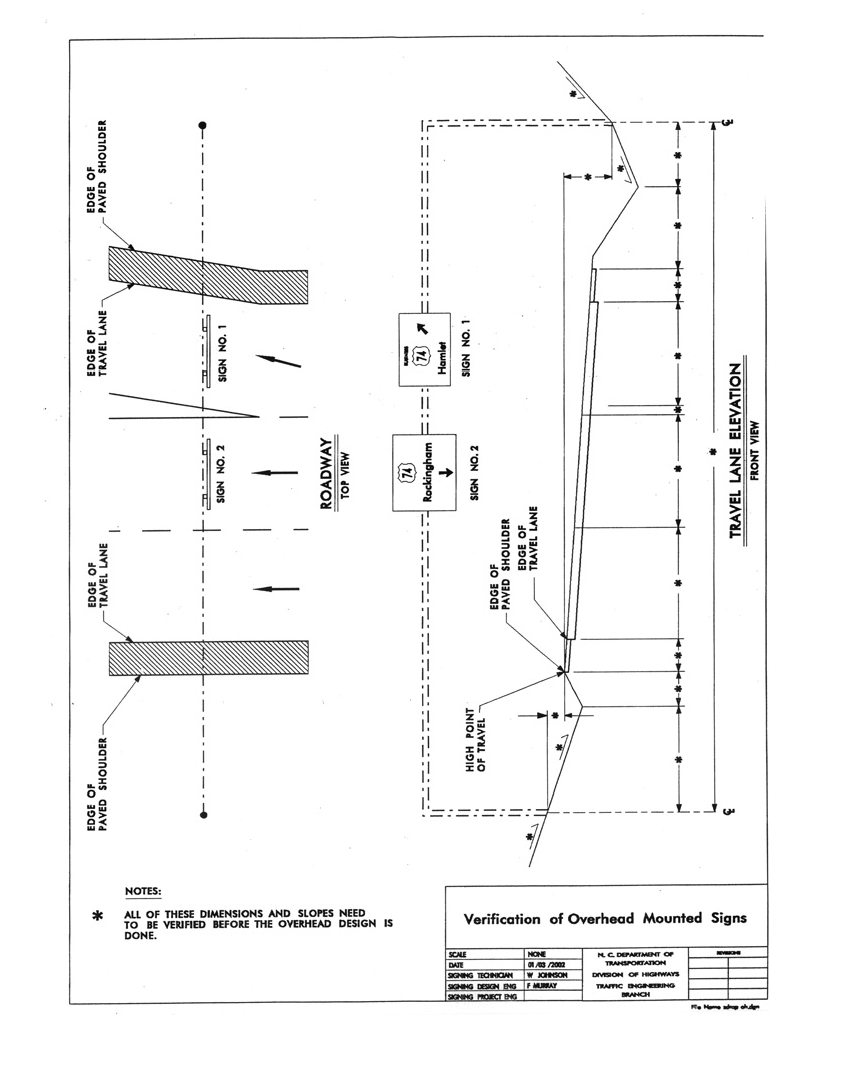
    Checking the information on overhead sign assemblies in the field will consist of “S” dimensions at the center of the structure upright supports, cut or fill slopes, and pavement width information. The “S” dimension for overheads is different from that of ground mounted signs. The elevation of the center of the upright is from the high point of the road. This includes paved shoulders, mountable medians, future lanes, or any point that a vehicle could physically drive on under any sign on the overhead structure. The side slope is the slope at the centerline of the uprights and at least 2 feet on both sides. Both the “S” dimension and the slopes are used by Structure Design to check the footing design. The width of each lane or part of a lane, shoulders, and the offset to the uprights should be verified. This is the cross section that the contractor will have to construct. See attached drawing on the proceeding page for clarification.
     
    For projects that have contract surveying, the Contractor will be responsible for providing this information to the Resident Engineer in accordance with Subarticle 801-2(H) of the 2012 Standard Specifications. The Resident Engineer will forward the information to the Signing Section for review and the design of the revised signing plans.
     
    Verifications of these dimensions must be made before supports for the ground mounted or overhead signs can be ordered by the contractor.
     
    ENGINEERING CONTROL - VERIFICATION OF OVERHEAD MOUNTED SIGNS.png
    STRUCTURE STAKEOUT
     
    Structure and Roadway plans should be studied together prior to beginning staking in order to become familiar with the planned work, to establish where reference points may be placed and remain undisturbed, to check lengths of box culverts as required on the culvert plans, and to check and recalculate slope, roadway widths, and elevations common to structure and adjacent roadway.
     
    During stakeout and construction of the structures, bound field or level books shall be used for structure work books in which shall be recorded: diagrams and sketches showing location of construction stakes set; complete level notes of elevations set for all parts of the structure and grade hubs; the names of all those doing the survey work, what each person did, and the date the work was done.
     
    Structures should be staked using the most accurate equipment and methods at the Resident Engineer's disposal. Total stations are preferred. Radial Stakeout should not be used for major structure stakeout. Control lines to be staked and referenced for bridges are: centerline or long chord line, end bent fill face lines, and interior bent centerlines, or other designated work lines. For box culverts the lines are: centerline of culvert and ends of barrel. Offset grade hubs should also be set for culverts. Hubs with tacks and clearly marked guard stakes shall be used to reference these lines. The Manual For Construction S​takeout should be followed.  There is also a Structure Layout video on the NCDOT YouTube channel.
     
    The sketches represent typical bridge and culvert layouts. They should be varied to suit individual cases. The links to the sketches can be found here: 


    Checking Layout
     
    When a structure is staked out by NCDOT staff, Resident Engineers and Party Chiefs should develop a systematic scheme for checking a structure stakeout both during the stakeout and after the structure has been laid out.  Each measurement, whether a distance, angle turned, or elevation given should be checked.  One scheme that will serve to check the work is to let entirely different personnel check the layout.  Another practical way to check the layout is to change roles within the survey party and perform a check of the layout.  This method will also serve to provide additional experience and training for party personnel.  When stakeout is performed by Contract Surveyors, an NCDOT survey party should perform a check of the structure layout.    
     
    Engineering Practices To Follow
     
    1. Check instruments periodically for accuracy.
       
    2. Check alignment stationing in the field from two independent references.
       
    3. Check bench marks in the field from two independent references. All bench marks which are established for use during construction should be, as nearly as practicable, of a permanent nature. Check bench marks used for structure construction with bench marks used for roadway construction. When setting bench marks, avoid setting them in deep embankments that have not set for several months or in any embankments in the vicinity of anticipated pile driving operations. This can be an inconvenience, but problems can arise due to settlement of the bench marks. Levels can be run from bench marks in other areas and temporary bench marks set, or checked, each time critical elevations are necessary, or at least once a week while in use except when pile driving has been taking place. If pile driving has taken place in the vicinity, the temporary bench marks set in embankments should be checked at least daily when in use.
       
    4. Completely stake structure when practicable before construction begins.
       
    5. Systematically and uniformly identify all points with clearly marked guard stakes.
       
    6. Set extra points to facilitate replacing those destroyed.
       
    7. Check railroad rail elevations against bottom of beam elevations at railroad separations during stakeout and compare difference in elevations to vertical clearance shown on plans.
       
    8. Check cut and fill slopes at end bents during and after grading but prior to starting structure construction.
       
    9. Immediately prior to casting the cap of a substructure unit, elevations are to be checked on the chamfer strip for each bridge seat. Immediately after all concrete in the cap has been cast, another check is to be made at each bridge seat using an independent set-up of the instrument. Any falsework slippage or excessive settlement will then be apparent. After the first substructure unit has been completed, both of the above checks shall include a check on a bridge seat of a previously cast cap. All rod readings and computations for the above shall be recorded, dated, and initialed in the structure field book.
       
    10. Check camber in beams and girders after they are erected but before connections are tightened. Beam camber shall be corrected to conform to 12 millimeters (1/2 inch) for proper tolerance.
       
    11. Check bridge slab thickness when the dry run is performed
       
    12. Check projection of shear studs into slab.
       
    13. Slope protection berm width should be computed prior to slope staking the ends of the bridge fills. The toe of the slope protection should be staked to insure that alignment and grade will conform with that of the roadway.
       
    14. It is usually good practice to establish a temporary bench mark on a substructure as soon as it is completed. This is usually accomplished by setting one temporary benchmark on a wing wall of each end bent.
       
    15. Check top of pavement elevations against bottom of beam elevation at flyovers during stakeout and compare difference in elevations to vertical clearance shown on plans to insure it is sufficient.

    SUGGESTED PROCEDURE FOR GRADING BUILD-UPS ON CONTINUOUS OR SIMPLE SPAN BRIDGES
     
    Final bottom of slab elevations at twentieth points between centerline of bearings are furnished by the Structures Management Unit. The elevations are given along the centerline of each girder and are used in computing the height of the build-ups. There is a video entitled Bridge Deck Buildups on the NCDOT YouTube channel.
     
    Build-up height is fixed at the centerline of bearing and would be constant throughout the length of a span if the actual girder camber was exactly as shown, but the build-ups will normally vary in height between bearings.
     
    Tops of girders should be marked with paint at each twentieth point. (For longer spans 40th or 60th points may be required – see construction elevations provided from the Structures Management Unit.) After camber has been checked, necessary corrections made, and diaphragm connection bolts tightened, elevations should be determined on top of girders at each twentieth point and used in computing build-up heights. The effect of the sun can significantly change girder camber. Levels should be run either early in the morning or on a completely overcast morning. Deflections shown in the deflection tables are used in the required computations. Build-up height at a twentieth point is computed as follows:
     
    + final bottom of slab elevation
    + deflection due to weight of slab
    + deflection due to weight of parapet, rail, and F.W.S.
    - top of girder elevation (determined in field)
     
    The algebraic sum of these values equals the height of build-up above the top of girder. In some cases, this value will be minus indicating the girder flange projects into the slab.  In such cases the Area Construction Engineer should be consulted.
     
    The build-up heights for the entire bridge can be computed and listed in a field book well in advance of any forming operation. These heights can be marked on the top of girder at the proper twentieth point.
     
    The Contractor should be made aware that the computed height is at the centerline of girder and will vary at each side of the build-up depending on the deck cross slope and flange width.
     
    Theoretical overhang elevations are no longer supplied and should not be used to grade overhangs.
     
    Overhangs can be graded very efficiently by using the overhang typical section and adjusting by a small amount of form settlement and compensating for build-ups on the top of the exterior girders or beams.  This can be done either with a “preacher” or checking the algebraic difference from the buildup to the overhang with an engineer’s level. There is a video entitled Overhangs​ on the NCDOT YouTube chanel.

     
    It should be noted that bridges with normal crown and similar overhangs on both sides can be graded using one typical section with the algebraic difference between the bottom of slab over the exterior girder or beam and the outside bottom edge of the overhang. A structure with constant superelevation will require two typical section computations. A structure with variable superelevation or varying width overhangs, such as those found on horizontally curved bridges with straight girders, will require a different typical section computation at each grade point if the superelevation or overhang width changes.
     
    Regardless of grade point spacing, all overhang brackets or jacks should be graded. A quick interpolation between grade points, with adjustment for top flange thickness when it changes, can be easily calculated.  String-lining between graded jacks to set other jacks is also acceptable.
     
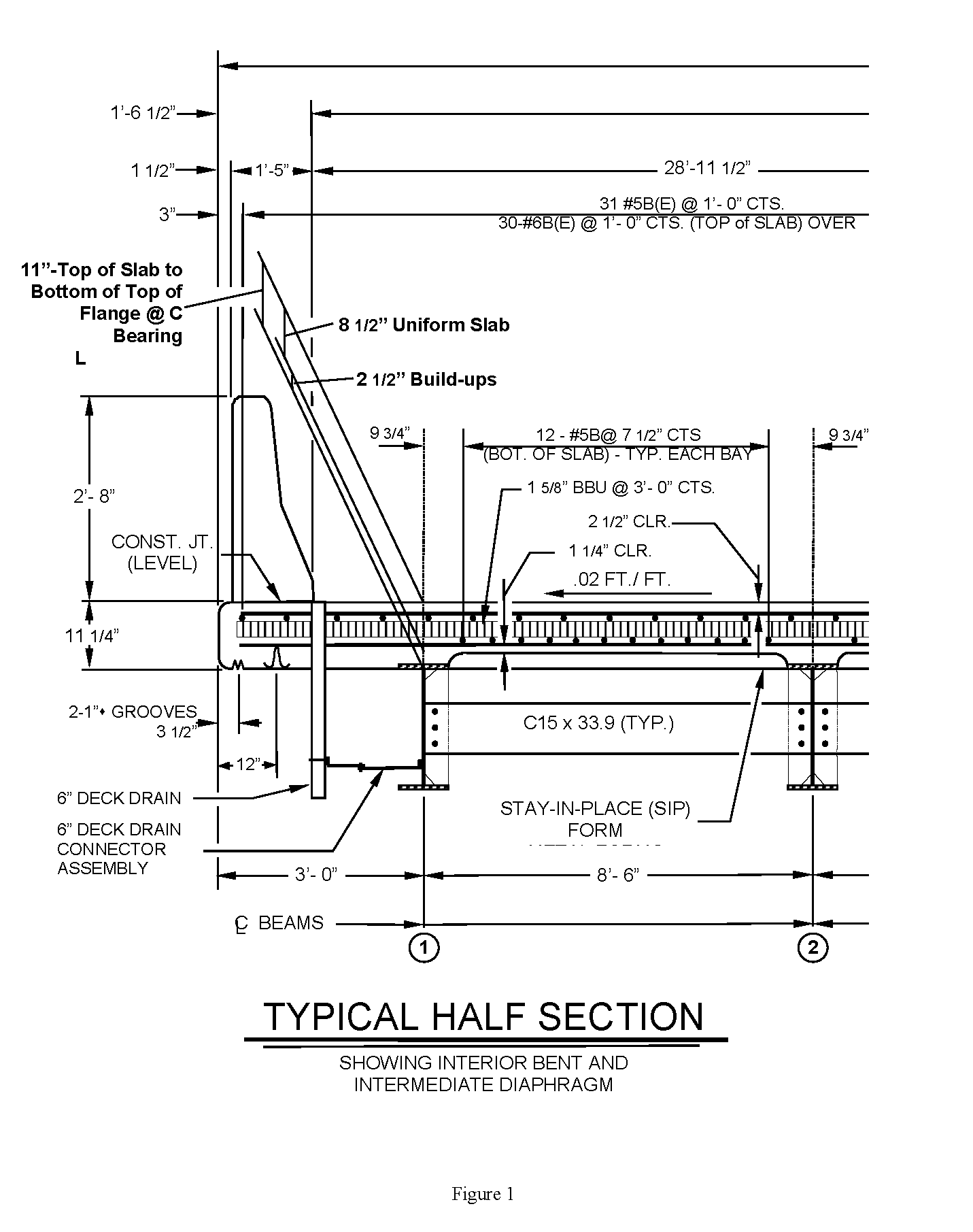
    Following is an example in English Units of using this method to grade overhang formwork: See Figure 1.
    ​​
    Step 1 - Compute algebraic difference between bottom of slab and outside bottom edge of overhang:
    Build Ups.PNG

    Therefore, grade for an overhang point opposite a field build-up of +0.12 = -0.24 + 0.12 = -0.12 below the top of beam or girder.
     
    Beginning in April 2017 the construction elevations were revised to provide the algebraic difference between the bottom of the slab over the centerline of the exterior girder and the outside edge of the overhang, eliminating the calculations above , with the exception of adding in form settlement.  The construction elevations would give the difference of -0.26’, and the +0.02 form settlement would then need to be added.

    Given this information the algebraic difference between the top of the girder and the overhang grade is easily determined.  Assuming the buildup at this location was 0.33' you would add the -0.26' above to the buildup, resulting in a difference of 0.07' from the top of the girder to the bottom of the overhang. 

    The construction elevations also show the distance from the centerline of the exterior girder to the overhang.  This information is especially useful when laying out the overhangs on a curved bridge with straight girders.  In such cases that the overhangs are laid out in this way you should pull a string down the center of the girder from bearing to bearing to locate the theoretical center of girder.  This is necessary due to potential sweep in the girder.   

    Step 2 - Show overhang grades in structure workbook opposite build-up grades and adjusted to level over from top of beam or girder with the use of an engineering level and rod or a carpenter level and rule. Interpolate in between grades to adjust each overhang bracket or jack to assure uniform grade. It is acceptable to string line between jacks at twentieth points which have been graded, to grade intermediate jacks. All grades can be computed and checked in the structure workbook well ahead of  time.
     
    The reason construction theoretical grades should not be used (and are no longer included in Construction Elevations) is to eliminate the effects temperature changes and the constant movement of girders or beams. Using typical sections will assure all overhangs are relative to the girder or beam and therefore a constant slope will be attained on the bottom of overhangs. In an extreme case, it would be possible to have a reverse slope on the overhang bottom if the girder or beam has moved sufficiently down and a theoretical elevation is used. 

    There is also a YouTube video discussing installation of Cast In Place Bridge Decking.
    ENGINEERING CONTROL - INTERIOR BENT.png 

    SUGGESTED PROCEDURE FOR GRADING HEADERS
     
    As of April 2017, header grades are no longer supplied in the construction elevations.  Better results are observed when the transverse screed is graded as outlined below and the header is left 1-2” low.  The screed is allowed to finish over the header to the proper grade.  
    If the contractor elects to use a longitudinal screed contact your Area Construction Engineer for guidance on setting header elevations.

    SUGGESTED PROCEDURE FOR GRADING SCREEDS
     
    A. Transverse Screed
     
    After overhang forms have been graded, the screed rail can be adjusted to some predetermined constant height above the bottom form at the outside edge of overhang. A gage stick and carpenter's level can be used in adjusting the screed rail to the proper elevation.
     
    The screed carriage must be graded to conform to the transverse slope of the deck, taking into consideration the weight of the operator and finishing mechanism.
     
    Dry runs should be made in accordance with the procedure at the end of this section to assure proper operation and slab thickness. Links to setup demonstration videos are also included in the procedure.  Pour direction and finishing direction can have drastic effects on the finish, and should be checked during the dry run and discussed at the Pre-Pour meeting. Ideally, the dry run should be performed before the Pre-Pour Meeting and the results discussed at the meeting.
     
    B. Longitudinal Screed
     
    Longitudinal Screeds are rarely used due to limited span length capability and the ease of grading transverse screeds. If a longitudinal screed is proposed to be used, contact the Area Construction Engineer to determine if it is an acceptable application and for assistance with reviewing the setup.
     
    The grade for the screed shall be computed accurately and set in the screed with an engineer’s level or a string line.  The shape of the screed should end up reflecting the vertical alignment of the road where the screed is set.  Computation of screed grades is somewhat complicated for continuous spans when a longitudinal screed is used.  Procedures included in the Engineering Control Section of this Manual are recommended.

     
    When using longitudinal screeds: the first interior bay should be loaded with concrete before loading the overhang.  This procedure will minimize unequal beam deflections.  As soon as the first overhang has been loaded and the deck concrete has been screeded beyond the second beam, the overhang shall be checked for grade.  For full pour simple spans, the grade should be checked with an Engineer's level.  For simple spans with multiple pours and continuous spans, the overhangs should be checked with a “preacher.”  Although the “preacher” does not assure exact final grades, it does assure smooth lines on the overhang.  Details for constructing a “preacher” are included in the aforementioned procedure for grading overhang forms, headers, etc.  If form adjustment is necessary, it should be made immediately.  The other overhang should be checked as soon as it is loaded.

     
    Dry Run Procedure for Transverse Screeds
    1. Screed Rails can be set initially by measuring up a constant distance from the overhang form or the top of the side form, but this is only preliminary.  Final adjustments must be made prior to the dry run.
    2. For more detailed discussion of screed setup see Chapter 4 of the Structures II (CON 815) Manual and view the Transverse Screed Setup videos on YouTube Construction Unit Training playlist​.  ​Before beginning, at all four corners of the screed, the distance from the screed rail up to the carriage rail should be the same and the carriage rail should be straightened (Video 1),  the rollers should be aligned (Video 2), and if the bridge is in a crown section, crown can be adjusted into the truss at this point (Video 3​).         

    3. The screed should be pulled to the zero buildup location of one exterior girders.  The distance from the buildup to the bottom edge of the front of the drums should be measured.  Both legs on this side of the screed should be adjusted identically until the distance measured is equal to the deck thickness plus the buildup.  This step should be repeated for the other exterior girder.  After this, the screed is set to grade (Video 4​).  
    4. Begin on one of the exterior girders.  At each 20th point (or 40th or 60th point on longer spans) use the stick constructed in Video 4 to measure up from the top of the girder to the carriage rail.  The carriage should be located as close to the exterior girder line you chose as possible and still allow for easy measurement.  This measurement should equal the calculated buildup.
    5. If the  buildup is greater than the calculated buildup, the screed rail should be lowered until the plan buildup is achieved.  Conversely, if the buildup is less than the plan thickness, the screed rail should be raised until the calculated buildup is achieved. The screed rail is adjusted by turning the nuts located between the top of the side form and the screed rail saddle. 
    6. Steps 4-5 should be repeated for each twentieth point on the exterior girders before checking the interior girders.  Any errors found on the interior girders at that point should be minor variations due to incorrect pan elevations or the arithmetic difference in the plan dead load deflection of the particular interior girder and that of the exterior girder.  
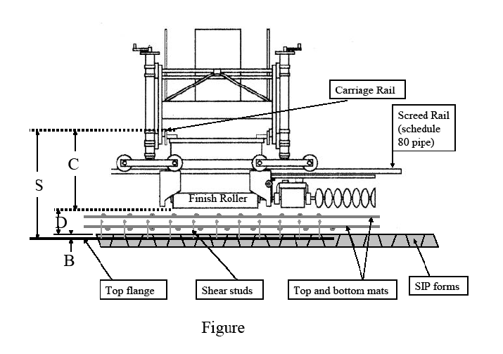
    7. Verify the plan deck thickness from the deck pans to the finish roller and the plan cover over the top mat of rebar.  The tolerance for deck thickness and rebar cover should be +/- 1/8th inch. The thickness and cover should be checked at least every other 20th point (or 40th or 60th point) at the center of the concrete deck panel or SIP form. 


    ENGINEERING CONTROL - SCREED.png  


No content found
No content found
No content found
No content found

Technician's Checklists

No content found

Materials

No content found

Measurement and Payment

No content found

‭(Hidden)‬ Related Documents

No content found
Was this page helpful?